Take a step forward in finite element analysis with
Mechanical Finder software!
All Together
Mechanical Finder includes all functions required for Quantitative CT based finite element analysis. This; DICOM import means you can seamlessly perform all procedures, such as segmentation, implant placement, mesh model creation, material selection, determination of boundary conditions, solving analyzes and results evaluation.
Inhomogeneous Materials
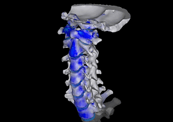
Finite element analysis of bone was performed with a two-layer model consisting of cortical bone and cancellous bone. However, the inhomogeneity of material properties is important for assessing bone stress and fracture. With Mechanical Finder, you can make completely non-homogeneous models.
Technical support
Since the purpose of finite element analysis of bone is based on medical requirements, it is difficult to understand what doctors want to do in the analysis with engineering background alone. Through conferences, analysis service and support, we have discussed and analyzed with doctors many times. With the experience we have gained, we provide not only support for using the software, but also analysis consultancy.
CT-Based Modeling
The 3D bone model can be created from DICOM data, thus projecting the patient-specific bone geometry into the model. A 3D model can be created by determining the area of interest (ROI) from the CT data through image processing or manual correction. In the created model, the patient's bone defects can be observed and the planned surgical procedure can be simulated.

Dynamic Analysis
In addition to static analysis, dynamic analysis that takes into account the inertia force can also be performed. By giving the initial velocity or adjusting the time-varying load, you can analyze short-term events such as collisions and impacts.

Nonlinear Material Analysis
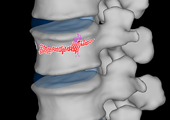
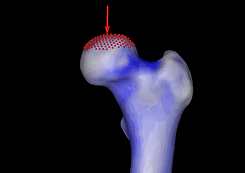
Nonlinear analyzes of plasticity and fracture mechanics of anatomical models can also be performed with Mechanical Finder. To evaluate clinical fractures with computer simulation, a tomography data with fracture line can be used or a fracture line can be created on the bone model. however, it is usually found as bone strength from the displacement load curve. There are some articles on cadaver experimental validation of finite element analysis.
Contact Analysis
The contact state between parts can be adjusted at the boundary of materials such as bone and implant. In addition, contact can be established between more than one material and the coefficient of friction can be defined between these contact surfaces. With the described frictional contact situation, it is possible to construct a more realistic model for the post-operative situation.

Analyzes Containing Geometric Nonlinearity
Not only analyzes based on small deformation theory, but also geometric nonlinear analyzes can be performed. Especially the analyzes with large deformations and rotations can be done accurately with the geometric nonlinear analysis method. In addition, soft tissues such as the intervertebral disc can be modeled with the superelastic material model.


Implant Application
Models such as implants, prostheses and geometries created from CT data are able to import in STL format. The position of the implant can be adjusted with the CT images surrounding the implant. In addition, the axis of rotation and the center of rotation of the implant models can be adjusted to easily place the models in the bone.
Shell and Truss Element
In addition to tetrahedral elements, it is possible to model shell and truss elements. Truss elements can be defined by the strain-strain relationship and are used to model ligaments in which the force only works in the tensile direction.
Image and Video
You can save the screen as an image at each step, such as defining material properties or displaying the result. There is also the function of recording the camera angle, which is convenient when comparing the results of different implant models. It can also be saved as a multiple frame video file. The videos on our website were created using this function.

Mesh Geometry
Bone geometry created via CT can be exported in STL format. At the same time, after creating a tetrahedral mesh, the surface mesh can be printed out and reused in other analyses.

Dental Implant Example
Program Usage Example
Recommended System Requirements
OS
Windows 8/10/11 (64bit)
Display
Resolution of 1280×1024 and above.
Processor
Intel® Core™ i7, i9, Intel® Xeon®
Storage
RAM
Standard Edition: 8GB and above Extended Edition: 16GB and above
*Analyzable model size depends on RAM memory size.
100 GB or more of disk space.
*Especially needed to save the project
(Project data can be saved to external storage.).
Graphic Card
External: NVIDIA®, AMD
Internal: Intel® Integrated Graphics
*AI segmentation requires NVIDIA graphics.


